Tri-Mer Corporation

The Tri-Mer portfolio includes more than 6000 air pollution control systems operating worldwide. Tri-Mer air pollution control systems serve semiconductor fab, pharmaceutical manufacturing, food and beverage processing and companies engaged in virtually every sector of manufacturing and the CPI. Manufacturing and technical support is provided exclusively from our 300,000 sq. ft. campus in central Michigan.
Tri-Mer's Catalytic Ceramic Filter system - UltraCat - is the premier dry system for simultaneously controlling multiple pollutants, including PM, SOx, and NOx. UltraCat ceramic filters are embedded with nanobits of NOx or VOC catalyst dispersed within the filter walls. Particulate (PM), SO2, HCl, metals such as Cr6, and NOx are removed by this proven, all-in-one system.
Tri-Mer's spectrum of wet equipment includes the Whirl/Wet dust collector, packed-bed tower scrubbers, crossflow scrubbers, chrome scrubbers, and the Tri-NOx Multi-Chem system for removal of NOx on applications involving low temperatures and high removal efficiency requirements.
Tri-Mer has one of America's largest fabrication facilities for PVC, polypropylene, and other industrial polymers. We specialize in process tanks up to 100' in length, ventilation, ducting, and workstations.
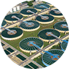
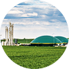
Biomass processing for W-T-E or incineration needs a predictable, efficient solution to air emissions. Proven scrubber technologies from Tri-Mer Corporation remove PM10, PM2.5, NOx, SO2, dioxins/furans, acid gases, metals - and odors.
All-dry catalytic and wet scrubber systems achieve virtually any target stack output. Tri-Mer is the technology of choice wherever air emissions are most restrictive.
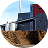
Tri-Mer Corp. will exhibit its “all-in-one” dry UltraCat and other biomass scrubber and dust collection technologies at The International Biomass Conference March 4-6.
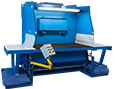
Tri-Nomic™ Downdraft Workstation combines ergonomic, fatigue-free use with best-available wet particle collection. Learn More.

